SCR (Silicon Controlled Rectifier),Current voltage characteristics of SCR, How many ways the SCR turns on ?

SCR (Silicon Controlled Rectifier) :

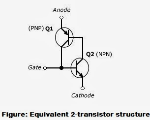
The silicon control rectifier is the oldest and most popular thyristor. It is an extremely reliable device and can be expected to deliver billions of operations before failure. The SCR (Silicon Controlled Rectifier) is built in one PNP and one NPN transistor.The basic structure of SCR is below.
The Transistor structure of a SCR
The equivalent two transistor structure is below


SCR volt-ampere characteristics curve
 
The SCR (Silicon Controlled Rectifier) Switch Turned on by five ways :
  1. By avalanche: When the anode is made much more positive then the cathode, Forward break over occurs and latch the device on.
  2. By rate of change: If the forward bias voltage across the device increases very quickly, a current will flow to charge the collector-base capacitance of the PNP transistor. This charging current represent base for the NPN transistor and turns it on
  3. By high temperature: Reversed-biased silicon junction show a leakage current that approximately doubles for every 8° C temperature rise.At some temperature, the leakage current will reach a level that latches the SCR on.
  4. By transistor action: This is the normal mode of operation for all but light-sensitive thyristors. An external gate pulse or signal is used to switch on the NPN transistor and latch the SCR.
  5. By light Energy: Light entering the junction area will release electron-hole pairs and letch the SCR on.

Wave, Wave properties, Elecromagnetic energy, propagation of Elecromagnetic waves,Signal phase, Impulse noise, Cross talk, Mechanical Waves,Thermal noise,Induced noise, Peak amplitude,Period and Frequency, Transmission Implements, Signal Attenuaton, Distortion, Wave free space loss, Signal noise,Analog and Digital Signal,Refraction,Properties of Light Signals,Properties of Electrical Signals,Types of Signals

Waves and Signals
Waves:
    Wave is defined as a disturbance or vibration that travels through a medium or vacuum from one to another location.This disturbance carries energy from one location to another. We can also describe wave as the transfer of energy from one location to another. Based on their mode of travel, waves are categorized into:

1. Electromagnetic Waves
     An Electromagnetic wave can travel through vacuum and does
   not require material medium for transmission. 

2. Mechanical Waves
   It can not travel through vacuum and needs a material medium
   for transmission. Modern communication systems use
   electromagnetic waves to transfer information.

Wave Properties:
   Waves have properties that affect the information carried by them.The various properties of a wave are -
  1.         Peak Amplitude
  2.         Period
  3.         Frequency
  4.         Wavelength
  5.         Phase
  6.         Speed of propagation.
Peak Amplitude: 
    The peak amplitude of a wave is the value of its highest intensity, proportional to the energy it carries.Neither the wavelength nor frequency of a wave depends on the amplitude.
 
Figure : Peak Amplitude

Period and Frequency:
      Period refers to the amount of time, in seconds, a wave needs to complete one cycle. The period of a waveis measured in seconds.The frequency of a wave refers to the number of periods in one second. Its unit is Hertz (Hz).
 Figure : Period frequency and wavelength of a wave


Phase:
     Position of a waveform relative to time to zero is called phase. It describes the amount of forward or backward shift along the time axis which indicates the status of the first cycle. Phase is calculated in degree or radian. The position of the waveform relative to time zero is called phase.

Electromagnetic Energy:
  Electrical energy or electromagnetic energy is a form of energy
  present in any electric field or magnetic field, or in any volume
  containing electromagnetic radiation.

Propagation of EM Waves:

 The two types of electromagnetic waves that are used to carry

 information are-


  1. Radio waves

  2. Light waves


  Based on the characteristics of propagation, radio waves are 

  divided into three categories -


  1. Ground waves

  2. Sky waves

  3. Line-of-sight waves

Transmission Impairments:

The four types of impairments are:

1. Attenuation.

2. Distortion.

3. Free space loss.

4. Noise.

Attenuation:  
Attenuation is the loss of energy or strength of a wave with distance
over any transmission medium or vacuum.

Figure : Attenuation

Distortion:
    Distortion refers to a change in the from or shape of a wave. A wave may have different frequency components may have different speed through the medium. This component may also different energies, and thus different attenuation. The attenuation typically is greater for higher frequency components, and causes additional distortion, known as attenuation distortion.
 
Figure : Distortion
Free space loss: 
The electromagnetic waves traveling through the atmosphere get 
dispersed with the distance traveled. The waves spread over a large 
area in the free space
Noise: 
Unwanted waves modify the waves carrying information during 
transmission. These unwanted waves are referred to as noise. Noise 
is divided into the following categories -
  1. Thermal noise

  2. Induced  noise

  3. Cross talk

  4. Impulse noise


Note: The random motion of electrons in a medium produces 
          thermal noise; thermal noise is also known as   white noise or      Johnson noise.

Types of Signals: 
The three types of signals used in telecommunications are

  1. Electrical signals

  2. Light signals

  3. Electromagnetic signals other than light (or radio waves)

Properties of Electrical Signals: 
  1.        Bandwidth of an Electrical Signal.
  2.        Data Rate of an Electrical Signal.       

Note:The absolute value of the difference between the lowest and    highest frequencies of a signal is called Bandwidth and the  range of that a signal spans from minimum to maximum is  called Spectrum.
Properties of Light Signals
      1.  Refraction     2.  Bandwidth   3.  Loss     4.  Data Rate
Refraction:

Figure : Bending of light ray
The two types of signals used in a telecommunication network are-
         1. Analog 
   2. Digital
Note: 1. Signal is the electrical representation of data. Signal and
              data both have analog and digital forms.
         2.  Analog signals take an infinite number of values in a range.         Digital signals take a limited number of values in a range.

Analog and Digital Signal:

 
Figure : (a) Analog signal (b) Digital signal


Communication Systems, Modulation,Types of modulation,Standards Organizations for communications,

 Communication Systems
Communication:
The term ‘communication’ refers to sending, receiving and process­ing of information by
electronic means.

 
Electronic communications started with wire telegraphy in the 1940s, developing into telephony some decades later. It used radio technology at the beginning of the past century after the invention of the triode tube. It subse­quently became even more widely used and refined through the invention and use of transistors, integrated circuits (ICs) and other semiconductor devices.
Communication System:
  • Message and Signal
  • Information Source
  • Transmitter
  • Channel-Noise
  • Receiver
  • Destination
Message and Signal:   

The massage is the information to be communicated. It can be sound, text, numbers, pictures or videos or any combination of these. On the other hand, signals are the electrical representation of messages.

Information source: 
  
Communication system exist  to convey a massage. the massage comes from the information source. i.e. information source generates the massage. The amount of information contained in any given massage can be measured in bits.

Transmitter:

Usually, the information generated by a source system is not transmitted directly in the from in which they are generated. Rather, a transmitter transforms and encodes the information in such a way as to produce electromagnetic signals that can be transmitted across some sort of transmission system.

Channel-noise:

It is inevitable that the signal will deteriorate during the process of transmission and reception as a result of some distortion in the system, or because of the introduction of noise, which is unwanted energy, usually a random character, present in a transmission system.

Receiver:

The receiver accept the signal from the transmission system and converts it into a from that can be handled by the destination device.

Destination:

Destination takes the incoming information from the receiver. Example: Loud speaker, video display unit, teletypewriter, various radar displays, television picture tube etc.
 
Block diagram of a communication system:


Figure : Block diagram of a communication system

Modulation:


Modulation is the process of putting information onto high-frequency carrier for
transmission.
 
In essence, the transmission takes place at the high frequency (the carrier) which has been
modified to carry the lower frequency information. The low frequency information is often 
called the intelligence signal or modulating signal.
 
It follows that once this information is received the signal must be removed from the high 
frequency carrier- a process called demodulation.

Need for Modulation:

There are three main hurdles in the process of such direct transmission of audio-frequency signals:
1. The signal range is relatively short.

2. If everybody started transmitting the low frequency signals directly, mutual 
    interference will render all of them ineffective. 

3. Size of the antenna required for efficient radiation of source signal would be
    large (i.e. about 75 km) as explained below.
 
Types of modulation: 


Figure : Types of modulation


Regulatory Agencies: 
  • All communications technology is subject to regulation by government agencies such as the Bangladesh Telecommunications Regulatory Commission (BTRC) in Bangladesh.
  • The pur­pose of these agencies is to protect the public interest by regulating radio, television, and wire/cable communications.
Standards Organizations: 
  • Institute of Electrical and Electronics Engineers (IEEE)
  • International Telecommunication Union - Telecommunication Standardization     Sector(ITU-T)  
  • International Organization for Standardization (ISO)
  • American National Standards Institute (ANSI)
  • Electronic Industries Association (EIA)


Bipolar Junction Transistor (BJT) , mode of operation , NPN Transistor , PNP Transistor

Bipolar Junction Transistor(BJT)


History:

The Bipolar Junction transistor(BJT) most famous electronic device in Integrated Circuit (IC). The invention of Bipolar Junction Transistor(BJT) in 1948 by Bell Telephone Laboratories. It was not until the 1970s and 1980s that is became a serious competitor to the Bipolar Junction transistor(BJT).

Which create a new era for the Electronic device history. In 2012, 60 million transistor were built for each man and women. Integrated circuit is not thinkable without it. Today digital world electronics device like smart phone, personal computer, telephone, calculator, televisions circuit board built by Bipolar Junction transistor(BJT).


Bipolar Junction Transistor(BJT):

Bipolar Junction Transistor(BJT) is one kind of semiconductor device that have three separately doped region. BJT is  three terminal device which called Emitter, Base and Collector. Generally BJT is used  to amplify, switch electronic signals and electrical power Oscillator.
There are two type of transistor :
                                                    (a) P-N-P transistor.
                                                    (b) N-P-N transistor.


BJT have two pn junctions. One is emitter-base Junction (EBJ) another one is Collector-base junction(CBJ). In forward and reverse bias condition different mode of operation of obtained. There are different mode of operation is given below:


PNP Transistor:

N-doped to the base between two P-Doped  region. A small current entering the base is amplified to produce a large to the collector and base.If the base is lower voltage than the emitter current flow from emitter to collector.


NPN Transistor:

P-doped on the base between two N-doped region. A small current entering the base is amplified to produce a large collector or emitter current. If the base as at a higher voltage then the emitter current flow collector to emitter.